Those mgds with two gate drive channel can have dual.
Low side gate driver application note.
Others can drive one high side and one low side power device.
It simplifies the design of control systems for a wide range of motor applications such as home appliances industrial drives dc motors and fans.
Table 3 shows the pin out definition for the output side for each of the gate drive modules pig out dn and pig out up.
Application note current sense operation configuration detection circuit ir212x gate driver ic.
Our gate driver solutions resources and expertise make it easier for you to design efficient reliable and power dense systems.
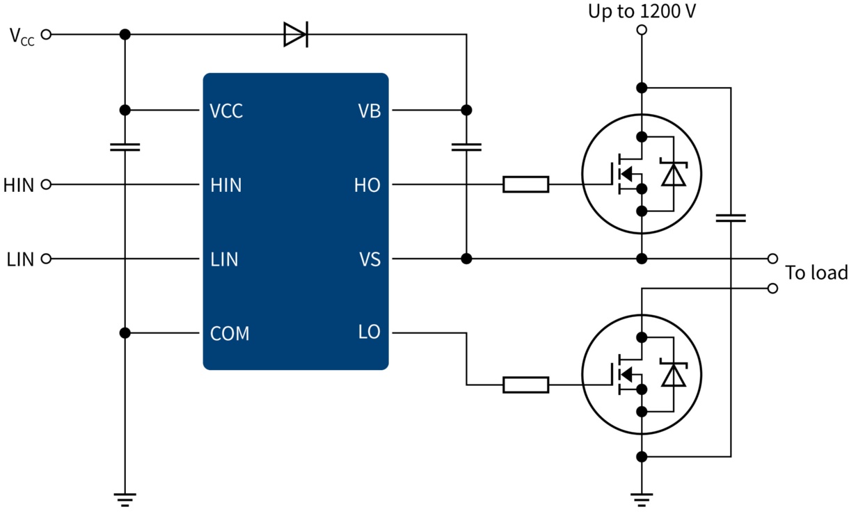
1 lin logic input for low side gate driver output 2 hin logic input for high side gate driver output 3 low side supply voltagevcc 4 low side returncom 5 low side gate drive outputlo.
This technical note compares the use of the ucc27517 and the discrete totem pole.
Low side gate drivers with uvlo versus bjt totem pole.
Replacing bjt totem pole with gate drivers has become increasingly popular due to the elimination of risks.
Application note 600 v high voltage high and low side gate driver bs2114f contents 1.
Gate drive evaluation platform.
Application note 5 revision 1 0 2016 11 11 mosfet driver ic basic considerations benefits of low side mosfet drivers in smps figure 5 standard mosfet drivers esd structure red have diodes which limit voltage range the voltage range of the input pins is important for the connection to the pwm source.
Application note l6390 half bridge gate driver introduction the l6390 is a versatile high voltage gate driver ic which is particularly suited for field oriented control foc motor driving applications.
It goes without saying that any high side driver can also drive a low side device.
It simplifies the design of control systems for a wide range of motor applications such as home appliances industrial drives dc motors and fans.
Others can drive a full three phase bridge e g the irs213x and irs263x families.
This application note contains the current sense operation configuration and detection circuit for ir212x gate driver ics.
Application note l6393 half bridge gate driver introduction the l6393 is a versatile high voltage gate driver ic particularly suited to motor driving applications.
Isolated drivers single and dual channel isolated gate drivers that can be used in low side high side or half bridge configurations with isolation up to 5 7 kvrms.
N compare the performance of different gate driver solutions under well defined and optimized test.